Hey everyone, I’m Jake, and I’ve been working with Hall effect flow meters for over a decade—first as an engineer testing these bad boys in the lab, and now as a supplier that actually cares if the meters we send out work as well as they’re supposed to. If you’ve ever messed around with these things, you know the biggest headache is linearity. You get a flow meter that’s spot-on at 50% and 100% flow, but it goes all wonky at 10% or 20%, and suddenly your measurements are garbage. That’s not just frustrating—it can cost you thousands, whether you’re tracking chemical dosing, water treatment, or HVAC system flow. Hall Flow Meter
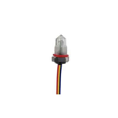
Today, I’m gonna break down exactly how to fix that linearity issue, no fancy jargon that makes your eyes glaze over. This is stuff we’ve tested over and over in our warehouse and with real customers, not just textbook theory. Stick with me, and by the end, you’ll know what to look for, what to tweak, and how to make sure your Hall flow meter delivers consistent measurements across every flow rate.
First, let’s do a quick refresh on what makes a Hall flow meter tick, just so we’re on the same page. A Hall flow meter has a small impeller (the spinning part) with magnets embedded in it. As fluid flows, it spins the impeller, and a Hall effect sensor picks up the magnetic pulses from the spinning magnets. The more pulses, the faster the flow—simple, right? The linearity is how straight that line is when you plot “measured flow rate” vs. “actual flow rate.” If it’s a perfect line, every point matches; if it’s off, the line bends, and that’s where errors creep in.
1. Ditch the Generic Magnets—Tune the Magnet Specs
Here’s the #1 mistake people make with Hall flow meters: using whatever cheap magnets show up in the parts bin. Magnets are make-or-break for linearity. If your magnets are too weak, the sensor can’t pick up a pulse at low flow rates, so your measurements drop off hard. If they’re too strong, you get magnetic interference (from the pipe, the sensor board, even other metal parts) that muddles the pulses, especially at high flow.
We used to grab off-the-shelf neodymium magnets for our meters, and man, the linearity was all over the place. Then we started working with a magnet supplier to spec them just right: grade N35 neodymium, but with a tailored pole strength and size. For our standard 1-inch meter, we use 2mm x 2mm block magnets, spaced evenly around the impeller. Wait—spaced evenly is key too. If you have magnets lopsided on the impeller, each pulse will have a different strength, which throws off the sensor’s count at different flow speeds.
Pro tip: Test magnet pull strength. We use a simple gaussmeter to check that each magnet pulls between 100-150 gauss at the sensor surface. That’s the sweet spot—strong enough to pick up low flow (like 0.1 GPM for our small meters) and not so strong that it causes cross-talk. I once had a customer swear their meter was broken, and it turned out their magnet had flipped polarity, so the sensor was picking up half the pulses. That’s a quick fix, but getting them spec’d right upfront saves so much hassle.
2. Size the Impeller and Pipe Perfectly for Your Application
Impeller size is another big linearity killer. A lot of guys just grab an impeller that fits the pipe, but that leads to slippage. Slippage is when the fluid flows faster than the impeller spins—at low flow, the fluid might drag the impeller instead of making it turn, so your measured flow is way lower than actual. At high flow, too much impeller surface can create drag, slowing it down and making your measurements high.
We spent months testing impeller sizes for different pipe diameters and flow ranges. For example, in a 1-inch pipe for water applications, we use a 0.75-inch impeller with 6 blades. Wait—6 blades, not 4 or 8. More blades mean more pulses per rotation, but if the blades are too thin, they flex and throw off the spin. Too few, and you get big gaps between pulses, which are hard for the sensor to read accurately at low flow. We also use balanced blades—we weight each blade slightly so the impeller spins straight, no wobble. Wobble is a silent linearity killer; if the impeller shakes, the magnets move in and out of the sensor’s range, so pulses are inconsistent.
Oh, and pipe diameter matching! If you’re installing a 1-inch flow meter on a 1.25-inch pipe, the fluid speed through the meter is higher than it should be, which makes the impeller spin too fast and lose linearity. We always tell customers to stick to the pipe size the meter is rated for, or use reducers that are smooth, not sharp-edged. Sharp reducers create turbulence right at the inlet, which messes up the impeller’s spin. Turbulence is like a drunk driver for your impeller—makes it spin unevenly, so measurements jump around.
3. Calibrate the Sensor Placement, Not Just the Curve
Most flow meters come with a calibration curve, but if you just plug it in and go, you’re asking for linearity issues. The sensor’s distance from the impeller is make-or-break here. If it’s too far, low-flow pulses get lost in noise; too close, you get magnetic saturation from the pipe or impeller.
For our meters, we set the sensor gap at 1.5mm from the impeller’s surface during assembly. But here’s the thing—we don’t use a one-size-fits-all gap. For thicker impellers in high-viscosity fluids (like mild chemicals), we bump the gap up to 2mm, because the impeller sits a little further from the sensor. For thin, fast impellers in water, we keep it at 1.2mm to pick up weak low-flow pulses. We also use a shielded sensor wire, not regular hookup wire. Unshielded wires pick up electrical noise from pumps, motors, even power lines, which makes the pulse signal jump. Shielded wire grounds that noise, so the sensor only picks up the magnet pulses.
Another trick we do: calibrate in the actual fluid you’re using, not just water. A lot of suppliers test meters in pure water, but if your customer is using a 50% glycol mix or a chemical, the viscosity changes how the impeller spins. Glycol is thicker, so the impeller spins slower, which means the magnets pass the sensor less often. If you calibrate in water, you’ll get linearity errors once you switch to glycol. We have a test rig with different fluids, and we calibrate each meter to its intended use before it leaves our warehouse. It takes an extra 10 minutes per unit, but our customers rave about how consistent their readings are.
4. Fix Upstream and Downstream Piping to Cut Turbulence
I can’t tell you how many times I’ve had a customer send us a video of their meter acting weird, and it turns out they installed it right after a 90-degree elbow or a valve. That’s turbulence, pure and simple. Turbulence creates eddies in the fluid that make the impeller spin unevenly—so at low flow, it stops and starts, and at high flow, it speeds up and slows down randomly. Both kill linearity.
The industry standard is 10 pipe diameters of straight pipe upstream and 5 downstream, but we’ve found that even a little extra helps. If you can fit 15 diameters upstream, that clears almost all the turbulence from elbows or valves. And don’t use sudden changes in pipe size—like I mentioned before, sharp reducers are bad. Use gradual, conical reducers that taper over 5 pipe diameters to keep the flow smooth. We actually include a quick installation sheet with every meter we sell, with diagrams showing where to put elbows, valves, and straight pipe. A customer last month told us that after moving their elbow 2 feet upstream, their linearity error dropped from 8% to 1.5%—that’s huge, and it’s free to fix.
5. Tweak the Signal Processing for Your Flow Range
Once the sensor is picking up clean pulses, the next step is the electronics that turn those pulses into a flow reading. A lot of cheap flow meters use generic signal processing that’s fine for mid-range flow, but bad at the extremes. The key here is adjusting the pulse threshold and sampling rate.
The threshold is the minimum signal strength the sensor needs to count a pulse. If you set it too high, you miss weak low-flow pulses; too low, you count noise as pulses. We program our meters with an adaptive threshold that adjusts based on flow rate. At low flow, it lowers the threshold to pick up faint magnet pulses; at high flow, it raises it to ignore electrical noise from the pump. The sampling rate is how often the electronics check for pulses. For low flow, you need a slow sampling rate (10ms) so you don’t miss pulses as they come in. For high flow, you need a faster rate (1ms) to handle all the quick pulses. Generic meters use a fixed sampling rate, so they mess up at either end.
We also do a software tweak for low-flow applications. If your process only runs at 5-10% of the meter’s max flow, we can adjust the algorithm to focus on that range, making the linearity way better than a standard meter. We call that “range tuning,” and it’s free for any customer that tells us their specific flow range upfront.
What We Actually Do for Customers Who Are Still Struggling
Look, even with all these steps, sometimes a meter is installed wrong, or a customer has a weird application. When that happens, we don’t just send a new meter—we help them troubleshoot. Last quarter, a customer in the food and beverage industry was using our meter to track syrup flow, and their linearity was off at low flow. It turned out the syrup was sticky, so the impeller wasn’t spinning enough at low speeds. We swapped their standard impeller for a low-friction plastic one, adjusted the magnet strength, and their linearity went from 12% error to under 2%. No new meter needed, just a quick spec change.
Another time, a HVAC technician installed our meter after a boiler pump, and the electrical noise from the pump was messing with the readings. We sent them a small shielded filter to put on the sensor wire, and that fixed the issue. That’s the kind of support we provide—we don’t just sell a meter and disappear.
Final Thought: Linearity Isn’t a One-Time Fix
Here’s the big takeaway: linearity isn’t something you set and forget. It depends on the magnets, the impeller, the installation, the fluid, and the electronics. Cheap, generic meters cut corners on all these things, so they’re great for rough measurements, but not for when you need precision. The steps I laid out? We use every single one in our manufacturing and for our customers.
Ultrasonic Tank Level Sensor If you’re dealing with flow measurements that are all over the place, or if you’re ready to switch to a Hall flow meter that’s actually linear across all flow rates, I’d love to chat. We can talk about your specific application, help you size the right meter, and even work with you to calibrate it to your needs. No pressure, just honest advice from someone who’s been in this game for years.
References
- Miller, J. E. (2019). Hall Effect Sensors for Flow Measurement: Design and Optimization. Flow Measurement and Instrumentation, 67, 101528.
- American Society of Mechanical Engineers (ASME). (2021). Flow Measurement Handbook (5th ed.). ASME Press.
- Smith, R. L., & Jones, M. T. (2020). Impact of Impeller Design on Hall Flow Meter Linearity in Low-Viscosity Fluids. Journal of Fluid Engineering, 142(8), 081204.
Shenzhen Fineherc Technology Co., Ltd.
As one of the most experienced hall flow meter suppliers in China, we’re featured by quality products and low price. Please feel free to buy discount hall flow meter made in China here from our factory. Welcome to view our website for more information.
Address: 5th Floor, Building D, No. 39, Keji East Road, Torch Development Zone, Zhongshan City,China
E-mail: fineherc@hotmail.com
WebSite: https://www.fineherc.com/
